Getting Started
Just bought a full Buzzpirat kit with everything included and want to start using it, but have no idea about mathematics, electronics, or hardware hacking? This is your starting point, let’s go!
What is the Buzzpirat?
The Buzzpirat is a hardware hacking tool that allows you to talk with chips. It is based on the Bus Pirate v3, a universal bus interface that talks to electronics from a computer serial terminal. The Buzzpirat is a Bus Pirate clone with a few modifications to make it more secure+complete for hardware hacking
What is hardware hacking?
Hardware Hacking is the art of breaking and/or modifying electronics for fun, profit, and the advancement of technology. Hardware hacking is not limited to electronics, but it often is. Other examples of hardware hacking include modifying cars, bicycles, and other mechanical systems.
Our first time communicating with a chip
Let’s start with a simple example. We will use the Buzzpirat to communicate with a chip and read its content. For this example, we will use a AT24C256 I2C EEPROM 5V board. This board is included in our full kit for practice purposes. You can purchase another one on Aliexpress, Amazon, or eBay.
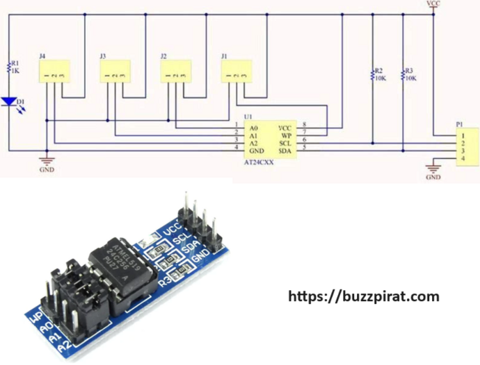
Intimidated by seeing a schematic and a board with lots of strange components? Don’t worry, we’ll take it step by step to understand what’s going on.
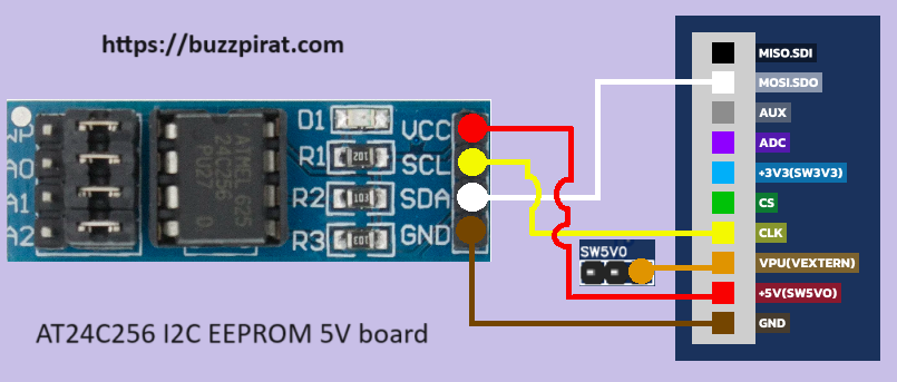
For this case, simply use the official Buzzpirat cables with the female Dupont connector they come with; there’s no need to use SMD IC clips. Connect the Buzzpirat to the AT24C256 board by attaching the +5v(SW5V0) to VCC, CLK to SCL, MOSI(SDA) to SDA, and GND to GND, ensuring each connection is secure for proper functionality.
Warning
Also, connect the VPU pin to a SW5V0 pin of the Buzzpirat.| Buzzpirat | AT24C256 board |
|---|---|
| +5v(SW5V0) | VCC |
| CLK | SCL |
| MOSI(SDA) | SDA |
| GND | GND |
| Buzzpirat | Buzzpirat |
|---|---|
| +5v(SW5V0) | VPU |

| MODE | MOSI | CLK | MISO | CS | AUX |
|---|---|---|---|---|---|
| HiZ | - | - | - | - | - |
| 1-Wire | OWD | - | - | - | - |
| UART | TX | - | RX | - | - |
| I2C | SDA | SCL | - | - | - |
| SPI | MOSI | CLK | MISO | CS | - |
| JTAG | TDI | TCK | TDO | TMS | - |
| AVR | MOSI | SCK | MISO | RESET | XTAL1 |
| PIC | PGD | PGC | - | MCLR | - |
| 2-Wire | OWD1 | OWD2 | - | - | - |
| 3-Wire | MOSI | CLK | MISO | CS | - |
| Pin Name | Description (Buzzpirat is the master) |
|---|---|
| MOSI | Master data out, slave in (SPI, JTAG), Serial data (1-Wire, I2C, KB), TX* (UART) |
| CLK | Clock signal (I2C, SPI, JTAG, KB) |
| MISO | Master data in, slave out (SPI, JTAG) RX (UART) |
| CS | Chip select (SPI), TMS (JTAG) |
| AUX | Auxiliary IO, frequency probe, pulse-width modulator |
| AUX-R | AUX-R is the AUX signal, but with a variable resistor of 10K+1K before reaching the pin |
| ADC | Voltage measurement probe (max 6volts) |
| VPU | Voltage input for on-board pull-up resistors (0-5volts). |
| TP0 | Auxiliary PIN connected to VPU |
| +1.8v(SW1V8) | +1.8volt switchable power supply |
| +2.5v(SW2V5) | +2.5volt switchable power supply |
| +3.3v(SW3V3) | +3.3volt switchable power supply |
| +5.0v(SW5V0) | +5volt switchable power supply |
| GND | Ground, connect to ground of test circuit |